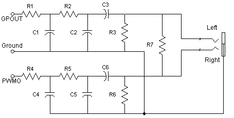
This is just an AC coupled attenuator , mix and low-pass filter. This makes the "hard" PWM stream into a soft audio signal with lots of benefits to the listener. You can hook a wire from the black wire (at buzzer side) to J4 (RS232 connector) pin 2 (not used). At cradle side you need to hook two wires, from pins 1 (ground/use black wire) and 2 (PWMO now/use red wire). My audio adapter can now be connected to the new cradle wires and to a small amplified multimedia speaker. Enjoy Pilot's new audio!

R1 = R2 =
R4 = R5 =
R3 =
R5 =
R7 =
C1 = C2 =
C4 = C5 =
C3 = C6 =
(Note: I'll define components values as soon as I can)
Ground = Cradle pin 1
PWMO = Cradle pin 2 after Pilot's modification
GPOUT = Cradle pin 10
To drive GPOUT we will need a special piece of software. This routine should toggle PG7 to create an audio stream like we
did on old computers (Apple, IBM XT, etc). This way you can add VOICE and/or more than one audio channel ! This will
be pretty cool !
The audio coming from buzzer will play louder at right channel and audio from GPOUT will play louder at left channel. R7 is
for panning these channels. R3 and R7 are for leveling outputs. I choose two separate filters for easy tuning. They are also two
steps (12dB/8a) for better response.
This circuit is very basic. If you are confortable with audio filters I'll be glad to hear from you. Keep in mind there is no power
supply !
[ Main Page ] [ How to open Page ] [ Enhancements Page ]