Q: How to connect Pilot's Cradle to a modem ?
A: You'll need a special adapter like this (you can buy parts at Radio Shack and build your own)
| DB9 Male to Cradle | DB25 Male to Modem |
|---|---|
| 1 | NC |
| 2 | 2 |
| 3 | 3 |
| 4 | NC |
| 5 | 7 |
| 6 | NC |
| 7 | 5 |
| 8 | 4 |
| 9 | NC |
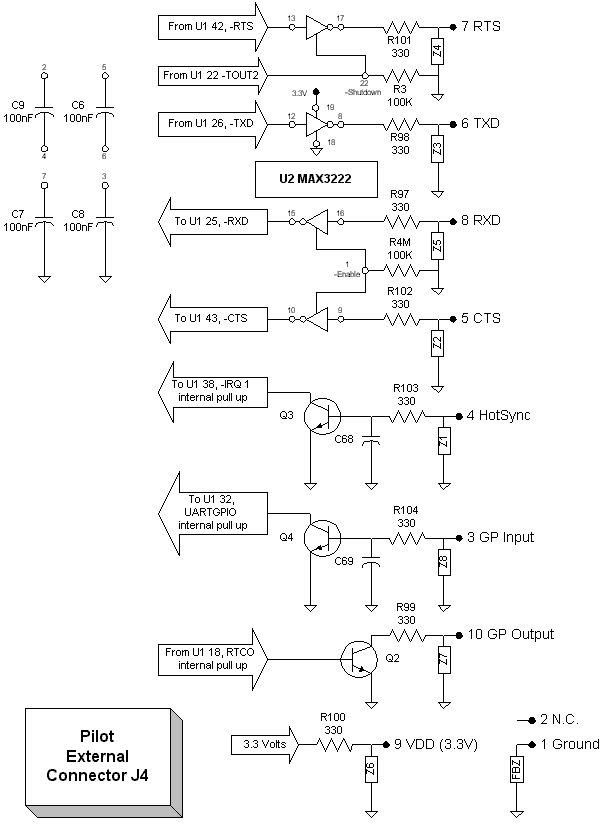
Your Pilot RS232 interface is the Maxim MAX3222 (3,3V low power RS232 transceivers).
This is the schematic diagram of RS232 interface of your Pilot. There is more than we can expect !

From this schematic we can see TIMER 2 is responsible for shutting power down. When we press HotSync button we are generating an interrupt vector 1. Remember HotSync button is just a momentary switch between pins 4 and 9. We also can read pin 3 state from UARTGPIO bit. We can toggle pin 10 state using PG7/RTCO bit. The FBZ component (I believe it means Ferrite Bead) has 0,2 ohms DC resistance. The other Z1 to 8 components have around 50K ohms DC resistance. They are hi frequency shunts to ground.
[ Next Page ] [ Previous Page ] [ Main Page ]